Bringing an old rotary phone back to life
My granduncle was an avid collector of old landline phones. After he sadly passed away last year, his phone collection was passed on to family members. I inherited one of these phones, and had the idea to bring it back to life as a usable landline phone for my home.
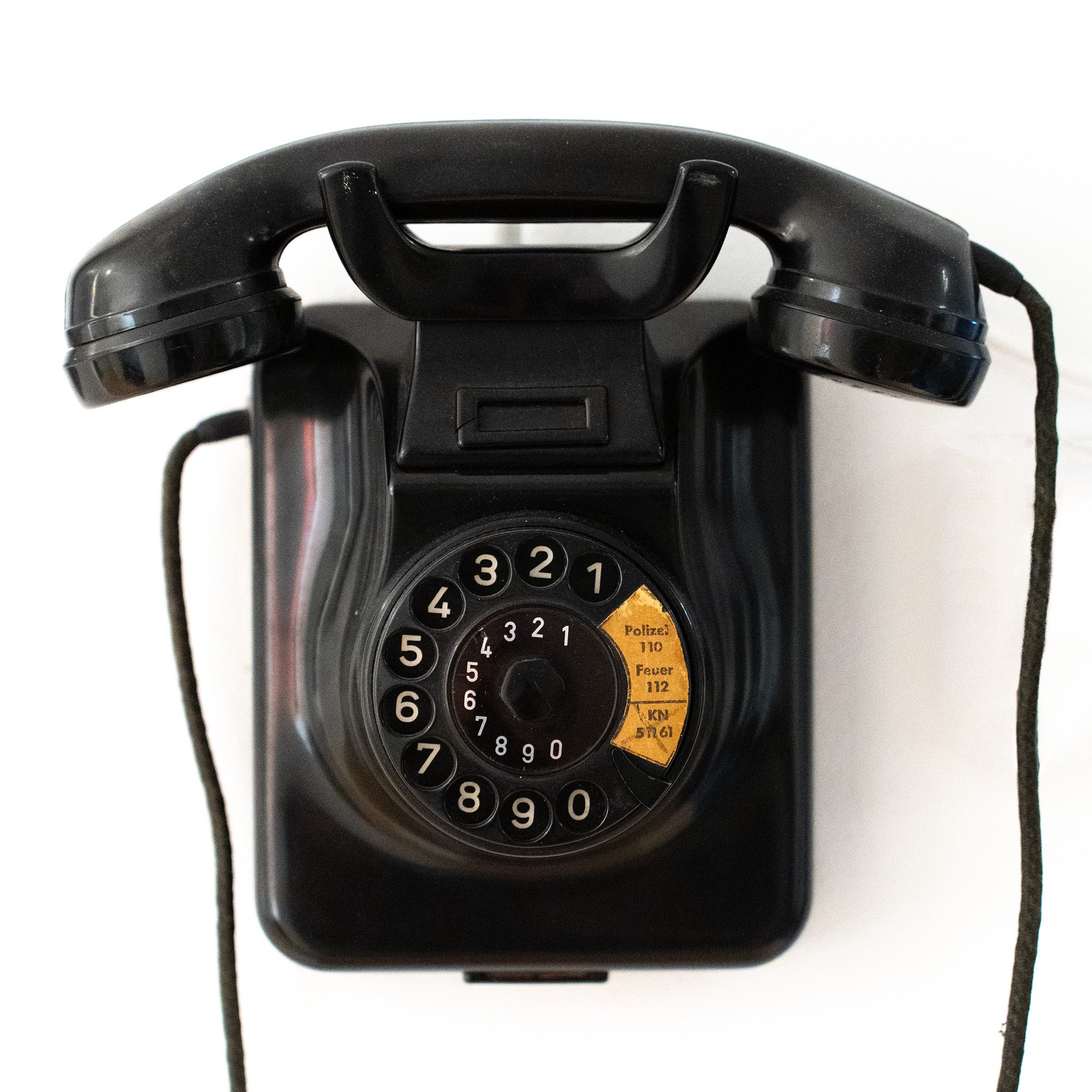
The phone I have is a W49, a model produced from 1949 to 1967 by Hagenuk in Kiel, Germany, by order of the Federal Post Office. This particular unit, according to the print on the backplate, was built in 1961. And it seems to actually have been used in the Kiel area, because in addition to the emergency numbers for police and fire department, the sticker on the rotary dial lists the former phone number of the local newspaper Kieler Nachrichten (KN).
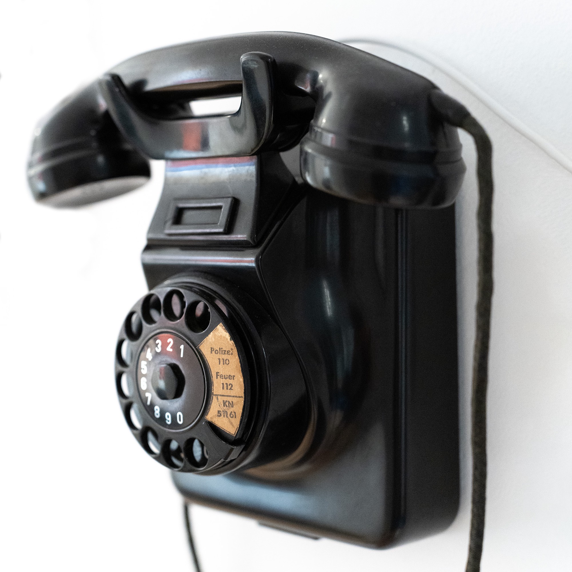
According to what I found online, the W49 is pretty much identical to the classic W48 developed by Siemens & Halske. The main special feature of the W49 is that its housing can be converted between desktop and wall-mounted modes by unscrewing the hook and the rotary dial and rotating each of them by 180°. A smart design!
Using rotary phones like this one on a modern German landline is not quite straightforward. They use an obsolete signaling system (pulse dialing / Impulswahlverfahren, IWV), which most modern equipment no longer supports. Also, the mechanical bell of the W49 requires a high current to operate. I could have bought an adapter to make it work, but I wanted to replace the phone’s inner workings with modern electronics, powered by a tiny Linux computer, the Raspberry Pi Zero 2W. The ability to run custom software on the Pi makes the phone much more unique and flexible: The Pi can connect wirelessly to my router to serve as a VoIP phone using the SIP protocol, and in the future I could still implement other features like Bluetooth tethering to a mobile phone or adding notification sounds and voice assistant / smart speaker functionality.
Opening it up
So, this is what I saw when I opened up the housing:
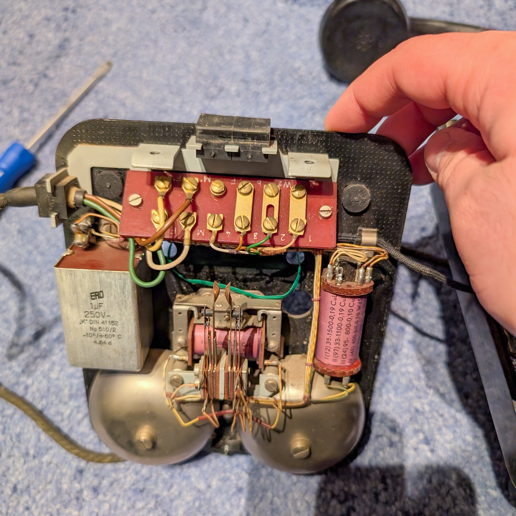
Two large bells for the ringer at the bottom, a terminal board for connecting various cables, and a few more electrical components (capacitor and coils). The original landline voltage included both DC power and an AC ringing signal (60 V at 25 Hz). The capacitor filtered out the DC component, so that when the AC ringer signal came in, it could drive the magnetic coil that makes the clapper ring the bells.
Just like the high-quality plastic housing, everything looked quite solid and well-made on the inside as well. I was especially impressed by the neat cable management (hand-tied pieces of yarn as cable ties). The massive 1 µF capacitor with metal housing also seems a bit bigger than what one would see in modern devices. One of the black rubber gaskets at the top would have been removed to make room to insert a telephone line cable.
First experiments
To check if my idea was feasible, I first tested how I could operate the individual components of the phone:
The handset
The handset contains the speaker and the microphone, and their four wires lead to the four leftmost connectors on the terminal board. To check if speaker and microphone could easily be driven with modern audio components, I took a spare cable with a TRRS audio jack, cut off the other end and hooked up the conductors to the corresponding wires on the terminal board. Once I had figured out the correct pin assignment, I could already play music from my phone through the earpiece and record audio from the microphone. The quality was surprisingly decent!
As the Pi Zero doesn’t have an integrated sound card, I figured the easiest solution would be to get a cheap USB-C to TRRS adapter and a Micro-USB to USB-C adapter.
The rotary dial
The rotary dial has another two pairs of wires leading to the terminal board. In this case, they are connected to two different switches in the dial mechanism. One of them signals when the dial is in use, while the other produces a number of pulses depending on how far the dial has been turned, where the number of pulses corresponds to the dialed number times two.
After connecting the two switches to GPIO pins of the Pi Zero and building a simple Python script to decode the signal, I managed to make the dial work:
A little bit of tweaking was necessary here to get the debouncing thresholds right, so that any additional stray pulses due to bouncing of the physical switches inside the dial would be rejected while still catching all of the actual pulses.
The ringer
The ringer requires a significant voltage and current to operate — after all, the landline ringer signal used to be 60 V AC. So I knew the 3.3 V GPIO pins from the Pi wouldn’t cut it on their own. However, I was able to make the clapper move a little using a 9 V battery connected to the magnetic coil, so this gave me hope that the voltage wouldn’t need to be quite as high to make it ring. It would still have to be an AC voltage though — not necessarily a sine wave, but at least somehow alternating between positive and negative polarity—otherwise, the magnetic coil would make the clapper only move in one direction and fail to hit the other bell.
I researched online for a compact and low-cost solution to achieve this, and finally ended up with a L298N motor driver board — a chip that can take a 12 V DC input and drive up to two outputs with 12 V in either direction controlled by GPIO signals supplied to the input pins. It even has a 5 V DC output that I can use to power the Pi, so I could power everything with a single power supply without a need for a separate DC-DC converter.
By adjusting the timing with which I applied GPIO signals to the L298N’s inputs, I was able to get a pretty satisfying ringing sound:
With different timings, I could even create different variations of the ringtone, such as longer and shorter rings, or even a slower “ding-dong”.
The hook switch
The hook switch was pretty easy to implement, it’s just another GPIO contact that opens and closes when the handset gets picked up or put back onto the hook. The switch contacts just needed some cleaning so that they would work reliably again.
On the original phone, the hook switch was attached to multiple switch contacts that were connected to different circuits. Now, I just needed a single contact, so I removed the extra wires from the other ones.
Putting it all together
Since I had now tested all the basic functionalities on their own, I started to integrate all the hardware into the housing. I removed the capacitor and coil on the sides, which were no longer needed, to make room for the Pi and the L298N. They were then attached to the existing screw holes in the baseplate with 3D-printed mounts. Then I connected everything with new wiring, using the original terminal board to keep it organized. I also 3D-printed a black insert that holds a 12 V power plug for the external power supply, replacing one of the two rubber gaskets at the top of the phone:
linphone SIP client to implement the actual VoIP calls. The USB audio adapter, which is wired
up to the handset, is configured as the default audio input and output.The final result
So there I had it: A working classic landline phone, ready to take phone calls in style 😎. And also, a platform for future experiments with the software to implement additional functionalities.
But most importantly: I had a lot of fun tinkering with the hardware, refreshing my electronics skills, learning more about the inner workings of rotary phones, and bringing old and new together.
Related content
Some related videos and blog posts that I found useful in the process: